
LAUNCH FLEET
BLITZSPEAR HIGH PERFORMANCE MINIMUM DIAMETER ROCKET
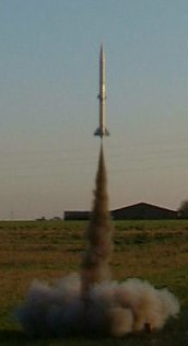
Blitzspear launching on
an I-80H hybrid motor
at EARS, June 2001
Photograph by Bob Arnott
BLITZSPEAR
Blitzspear was a high performance, high altitude rocket. The rocket was a 54mm, minimum diameter rocket, designed to take 54mm diameter motors up to, and including, an Aerotech K-700W. The idea behind Blitzspear was quite simply, to take and hold all HPR altitude and speed records for 54mm diameter motors (i.e. J-class and K-class) in the U.K.
The existing UK HPR records for the various motor classes were neither set by, or held by, minimum diameter rockets in most cases, but more often than not, were held by kits. I felt that the envelope needed to be pushed a bit, so a bit more ingenuity than setting an altitude record with a kit or a fat rocket would be required. The obvious solution would be to use a minimum diameter design, with a smooth finish, and minimum of external protuberances. This design would reduce skin drag, parasitic drag and the minimum diameter design would reduce the frontal area too.
The rocket was modelled thoroughly on Rocksim first, with more than a hundred 4th order Runge-Kutta simulations being run to determine the best design compromise for the vehicle.
In order to fly the rocket on the most powerful motors possible, no expense was spared on the construction. The rocket was constructed almost completely from fibreglass (with the fibreglass airframe tubes and coupler tubes from Giant Leap Rocketry), with aluminium and stainless steel sub-components in non critical areas, a Pete's Rockets 54mm diameter aluminium motor retainer and a Dupont Zytel ACME fin canister (from Pete's Rockets).
Again, because it was to be used for potential altitude record setting flights, and generally for high altitude flights, nothing could be left to chance. The rocket was designed for multiple redundancy, with twin ejection systems for both the drogue and main recovery systems, as well as twin altimeters for recovery system deployment.
Payload Section
For the main payload bay module and the ejection system, I had taken notes from the methods used by a number of other UK rocketeers, most notably, Robin Tomes, Bob Arnott and Pete Davy. Even though their payload sections were extremely good, I was determined to improve on them.
The fibreglass payload bay had one bulkhead permanently fitted in place by Dev-con 2-ton epoxy. The other bulkhead was retained by 4 countersunk screws and by M4 bolts attaching to 2 lengths of steel M4 studding which was permanently fitted to one bulkhead by Dev-con 2-ton epoxy, and bolted at the other end after the other bulkhead is screwed into position, and the M4 studding was passed through 2 holes in the other bulkhead designed to allow it to pass through for bolting. This system provided tremendous strength for shock loadings at drogue and main parachute deployment, and also allowed easy access to the avionics in the payload bay for modification, programming or prepping.
The bulkheads were equipped with twin LES/Safeject holders epoxied to the bulkheads, with hard mounted M3 screws epoxied in place for the use of the Safeject holders. Each bulkhead was fitted with a main M5 U-bolt onto which a Quick-Link could be attached for the recovery system. The positioning of the U-bolt and an attached Quick-Link was designed so that the Quick-Link would clear the LES/Safeject holders on either side of the U-bolt.
There were 2 x 5mm diameter aluminium tubes also fitted and epoxied into the bulkhead to enable igniters to be easily threaded into the payload bay, and to prevent gases from the expulsion charges from being directed into the payload bay. The reason for using 2 aluminium tubes was that so each igniter to each separate LES/Safeject holder passes through a separate tube to prevent confusion.
The payload section was 12 inches long, and was designed to accommodate an AED R-DAS flight computer, a G-Wiz LC Deluxe altimeter/accelerometer, a Blacksky Research ALTACC altimeter/accelerometer and a MARS MkII 433 MHz telemetry module.
Recovery System
The recovery system consisted of a 2-stage recovery system, with a PML streamer deployed at apogee from a 10 inch long drogue/streamer section (6 inches useable volume), and a main parachute deployed at low altitude from an 18 inch long (14 inches useable volume) main parachute section. 4mm diameter kernmantle climbing cord was used for the shock cord, with a 3 metre length used for the drogue/streamer section and a 4 metre length used for the main parachute section. Both drogue and main sections are also equipped with Nomex flame shields to protect the parachutes.
A Nomex flameshield was a simpler method of parachute protection than either a piston or an exhaust baffle, and provides a simple method of protection (simple is generally good for high performance rockets, where it is often a good idea to reduce the number of things that can go wrong).
The ejection system used 2 Safeject holders for each parachute or streamer. Each Safeject holder contained an electric match which is wired to an altimeter. Having 2 Safeject holders for each stage of recovery allowed 2 independent altimeters to be used for deployment, with each altimeter wired up to a different electric match and Safeject holder.
Motor Section
The motor section consisted of a fibreglass tube section with an ACME fin canister epoxied to it with Dev-con 2-ton epoxy, and a bulkhead fitted with an M5 U-Bolt to provide the motor section with an anti-zipper design. The fin canister was faired into the fibreglass tube using P38, and because of the fin canister's greater diameter than the fibreglass tube, a small fibreglass powerbulge was constructed at the other end of the fibreglass motor tube, and faired in with P38, this allowed accurate placement for rail-guides (a rail launcher is the method of launch for the rocket, since it is more rigid than a rod based launcher). A Pete's Rockets 54mm diameter aluminium motor retainer was epoxied with Dev-con 2-ton epoxy onto the end of the motor tube, to prevent the motor from sliding out of the rocket.
Thanks must go to Iain Colledge who blended the fin canister transition and power bulge with his Dremel sander, and did a wonderful job.
Finishing
The rocket was first spray painted with 4 coats of car primer sprayed on from a spraygun fitted to a compressor system. In between each layer, the airframe was sanded down lightly with 240 grit wet n dry. The rocket was then spray painted with the gloss colours. Again, the airframe was lightly sanded between each layer sprayed on. The main colour used was gloss orange for easy visibility. The payload section was painted with gloss black and white tracking stripes, and the nosecone was painted gloss black.
Naming
The name of the rocket came from a spacecraft called Blitzspear in 2000AD. Given that the rocket was long and spear like, would travel at speeds in excess of Mach 1 on the more powerful motors, this seemed to be an apt name.
Specifications
| Diameter | 54mm |
| Length | 2000mm |
| Motor Mount | 54mm |
| Airframe Material | Pure fibreglass |
| Number of fins and fin geometry | 3 Clipped diamond |
| Recovery System | 2-stage PML Streamer at apogee PML 4 foot diameter Main Parachute at low altitude |
| Dry Mass | TBA |
| Avionics | 1, or more of the following:
|
Launches
| Launch | Avionics | Propulsion | Recovery |
| 1 | ALTACC | I-80H | Single Stage Rocketman R3C Pro-XP |
| 2 | ALTACC | I-80H | Single Stage Rocketman R3C Pro-XP |
| 3 | G-Wiz LC Deluxe | I-80H | Single Stage Rocketman R3C Pro-XP |
| 4 | R-DAS ALTACC |
I-80H | Single Stage Rocketman R3C Pro-XP |
| 5 | R-DAS ALTACC |
J-200 | 2-Stage PML Streamer Rocketman R3C Pro-XP |
See Also
PML AMRAAM 3, PML Patriot, LOC Caliber, LOC IV, PML Phobos, Blitzspear, Hytest, Get Real
