
LIQUID PROPELLANT ROCKET PROPULSION
With my interests in rocket propulsion, I have developed a number of liquid propulsion systems in the past (with varying degrees of success). However, when the opportunity arose, I decided to buy a commercially available liquid bi-propellant rocket engine - The Systeme Solaire SS67B3 liquid rocket engine. The Systeme Solaire liquid rocket engine is a pressure fed (using Carbon Dioxide as the pressurant) rocket engine, and uses petrol (gasoline) as the fuel, and 50% Hydrogen Peroxide (H2O2) as the oxidiser, with a slurry "cake" of potassium permanganate coated over the flame holder in the combustion chamber to decompose the hydrogen peroxide when it enters the combustion chamber.
Ignition is achieved by using a solid rocket motor propellant grain with an electrical igniter fitted into the propellant grain, and then this igniter assembly is placed into the centre of the combustion chamber.
It is also possible to use paraffin (kerosene) as the fuel for the Systeme Solaire rocket engine. In terms of High Power Rocketry classification, the rocket engine is K-class to L-class, depending on the propellant mixture.
The version of the liquid rocket engine I have, has been modified by the manufacturers to include an additional valve which allows direct filling of the Carbon Dioxide pressurisation tank from commercially available pressurised tanks. The addition of a further valve also enables remote filling of the pressurisation tank as well, which makes the system safer. Personally, I would not want to take the risk of following the standard launch procedure - whilst it is safe enough in theory, there are a number of potential failure modes, any one of which could result in problems.
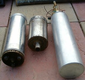
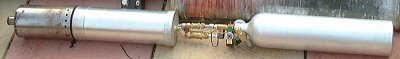
Figure 1: Systeme Solaire SS67B3
The Systeme Solaire SS67B3 liquid rocket engine is composed of 3 main sections:
- The Fuel and Oxidiser Tank Assembly
- The Combustion Chamber
- The Pressurisation Tank and rocket plumbing
Containing the Petrol and the Hydrogen Peroxide in the concentric tanks
Containing the flame holder which is coated with the potassium permanganate "cake" before launch, and the igniter. The small nozzle is seen closest to the front in this photo
Containing Carbon Dioxide in the pressurisation tank, and with the plumbing shown at the rear in this photo
The photograph shows the Fuel and Oxidiser Tank assembly on the left, the combustion chamber assembly in the centre, and the Carbon Dioxide pressurisation tank and rocket plumbing on the right.
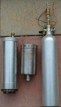
Figure 2: Systeme Solaire SS67B3
The Fuel and Oxidiser Tank Assembly
The Fuel and Oxidiser Tank assembly consists of a central tank for the fuel, and a tank around the outside of the inner tank acting as a jacket, and containing the oxidiser. The tanks are welded into place, and at the end which mates to the combustion chamber, there is one central injector for the fuel, and 4 injectors for the oxidiser.
The injectors use spring loaded valves, which keep the injectors closed until the ignition sequence starts, at which point, with the fuel and oxidiser now under pressure, the valves are forced open by the high pressure Carbon Dioxide in the pressurisation tank, and the fuel and oxidiser is injected into the combustion chamber.
The Hydrogen Peroxide forced through the oxidiser injectors impinges upon a slurry "cake" of potassium permanganate coated over the flame holder in the combustion chamber, causing the decomposition of the hydrogen peroxide.
The connections from the tanks to the pressurisation system are standard Swagelok fittings.
The photograph shows the Fuel and Oxidiser Tank assembly on the left, the combustion chamber assembly in the centre, and the pressurisation tank and rocket plumbing on the right.
Figure 3: Systeme Solaire SS67B3
Airframe
The airframe supplied with the Systeme Solaire liquid rocket engine is a lightweight, single section cardboard tube of 110mm external diameter (The Systeme Solaire liquid rocket engine is just too wide to fit in a standard 4 inch diameter High Power Rocket airframe tube). There are 3 fibreglass G-10 delta fins which are surface mounted to the airframe, and a modified 4 inch diameter nosecone.
The airframe tube does not seem to be as good quality as the airframe tubes manufactured by rocketry companies such as LOC-Precision or PML, although the Systeme Solaire airframe tube is certainly lightweight. I took one look at the quality of the airframe with the Systeme Solaire, and decided to go with something else to house the liquid propellant engine. I am currently building yet another airframe for the Systeme Solaire based on 125mm diameter carbon fibre airframe tube instead of the supplied airframe tube, and augmenting the low thrust of the System Solaire rocket engine with additional solid rocket booster motors (Cesaroni Pro-38 solid rocket motors).
Recovery
As the Systeme Solaire liquid rocket engine is supplied, the recovery system is designed to make use of drag separation at main engine cut-off, effecting nosecone removal and the parachute being pulled out. This is clearly a fairly marginal recovery method however, and it is strongly recommended that a recovery system with electronic ejection via an altimeter is used. My standard avionics system which I am using for the Systeme Solaire consists of an AED Compact R-DAS Flight Computer and a G-Wiz LC Deluxe Altimeter/ Accelerometer, since these units can normally cope with pretty much anything thrown at them, and still get the parachutes out. The ejection charges are fitted in Spacetec SafeEject canisters.
Rocket Plumbing
The main visual difference between the Systeme Solaire liquid rocket engine and more familiar solid and hybrid motors in amateur rocketry, is the plumbing. The plumbing for the transfer of the fuel and oxidiser to the combustion chamber, is as good as non existent, thanks to the ingenious toroidal tanking system this engine uses. However, plumbing is required from the pressurisation tank to the fuel and oxidiser tanks.
The flow line from the pressurisation tank first runs through a fill valve (not included as standard, but added to provide a means of direct filling of the tank). The flow line then runs through a servo powered valve which opens during the ignition sequence. The servo is inititiated by a 12 volt pulse (which can be controlled from a launch controller remotely), which drives the servo which opens the valve. Beneath the servo driven valve, the plumbing splits into 2 separate pipes, one which screws into the fuel tank, and one which screws into the oxidiser tank.
Thrust to Weight Ratio
The thrust to weight ratio of the standard rocket supplied with the Systeme Solaire rocket engine is not great. The Gross Lift Off Mass is 7.1 kilograms, and the average thrust of the engine is 260 Newtons. Personally, given a standard build, I would not launch the rocket on less than a 12 foot launch rail in calm weather, because of the safety aspects. Given any extra mass added to the rocket (stonger airframe, onboard avionics etc), it would be highly advisable to use additional rocket motors for boosting the rocket off the launch pad. The lower thrust to weight ratio resulting from a heavier rocket would make the flight performance marginal at best, and the performance is already pretty marginal to start with.
Complexity
It should be noted, the Systeme Solaire liquid rocket engine is most definitely not for the faint hearted, or for anyone experiencing problems with construction or operation of standard solid or hybrid rocket motors. The Systeme Solaire liquid rocket engine is considerably more complicated than either a solid or a hybrid rocket motor, and involves considerable preparation time, and even then, can be temperamental to get started. It is not excessively complicated, just sufficiently complicated to make it an advanced project in terms of High Power Rocketry.
Is this dangerous?
A pressurised liquid rocket engine shares a lot in common with mixed gas brazing and welding sets. In many respects, it is safer, since when you ignite it, you are doing so remotely rather than being stood right next to it as you would with brazing and welding sets.
The safety issues of major concern with a liquid rocket engine such as the Systeme Solaire are mainly concerned with the oxidiser, Hydrogen Peroxide. At 50% strength, it is not as reactive as 80%-90% strength Hydrogen Peroxide, however, it is still not a pleasant substance to get anywhere near your skin, and for this reason, appropriate, non reactive, protective gloves should be worn when transferring Hydrogen Peroxide to the oxidiser tank. Similarly, the catalyst for the Hydrogen Peroxide, Potassium Permanganate, leaves a very nasty purple stain on anything it comes into contact with, especially skin, so it is essential to wear gloves when either making the catalyst pack, or cleaning the residue from the combustion chamber after use.
As with any system involving reactive chemicals and / or pressurised gases, as long as the system is treated with lots of respect, and a mature, intelligent and methodical approach is followed, then any potential hazards can be minimised.
THE TAIFUN MISSILE
The Systeme Solaire SS67B1, B2 and B3 liquid rocket engines are based on the World War 2 German EMW Taifun missile rocket engine.
The Elektromechanische Werke (EMW) Taifun Missile was an unguided, Surface to Air missile, based on a barrage rocket, and depending on spin stabilisation for guidance. The Taifun was designed to be mass produced and to be fired in salvos.
Length: 1.93 metres (6.3 feet)
Range: 7.5 miles
Maximum Speed: 2800 miles per hour
Maximum Altitude: 5 miles
Surviving examples of the Taifun missile are on display at RAF Cosford.
REFERENCES
See Also
Hybrid Rocket Science, Hybrid Rocket Help Clinic, Amateur Hybrid Motors, Amateur Liquid Rockets, Guidance, Gimballed Motors, Launch Controller, UK Rocketry Vendors, UK Rocket Groups, UK Space Organisations
