
CREATIVE SCIENCE EXPERIMENTS
HOW TO GET EXTREME RANGE FROM A VIDEO SENDER OR FROM A WIRELESS LAN TRANSMITTER.
DIY S-band (2.4GHz) Helical Antenna
 Disclaimer: Don't modify the transmitter at all if you are in the U.K. (I don't know the laws for any other countries). Doing so in the U.K. is against the law. You could add a receive antenna on the size of Jodrell Bank if you want, just don't modify the transmitter. You are allowed to transmit at a power of up to 10 miliWatts or 10 dBm at this frequency in the U.K. but any more than this is a big no-no.
Yes, Boys and Girls, for little more than a couple of pints of beer (well if you pay the extortionate prices in London, anyway), you too could site your TV 2-3 miles away from your video, or connect to your wireless LAN from the middle of a field.
The key to this wonder of modern technology, if you want to watch TV rather a long distance from your video, is a video sender unit, of the type that can be bought in most major electronics stores for under 100 pounds sterling. If you want to play Quake whilst sat in a field a few miles away from your base station you will need wireless LAN hardware which is slightly more expensive, but the principal remains the same.
CHOOSING THE RECEIVER ANTENNA
Having acquired a video sender transmitter and receiver, the next step is to crank up the range. In the U.K. legally, you can only do this by using a different receiver and/or receiver antenna, and not by breaking open the transmitter can and beefing up the power output or putting high gain antennas on the transmitter. In this case, money was tight, so in order to keep costs as low as possible, this meant that only modifying the receiver antenna was considered, and not getting a whole new receiver.
O.K. paragraph of geekspeak: The options for receiver antenna were; a dipole, a patch antenna, or a Quadrifilar Helix. A dipole is a linearly polarised antenna and would work best to a Yagi antenna (similar to those used on the top of houses to receive TV signals). A circularly polarised patch is not omnidirectional, but this and a QF helix would work best to a helical receive antenna. Circularly Polarised to Circularly Polarised or linear to linear is best. If mismatched transmit and receive antennas are used, it will work but will be about 6dB less efficient. A QF helix has the major advantage that it transmits circularly polarised radiation but omnidirectional about its axis, because of this reason, a QF helix was chosen as the receiver antenna.
With the choice of antenna determined, the next stage was to work out how to construct the antenna. For construction, Jason Hecker from Canberra, Australia, has put together a superb construction article on the web.
ANTENNA CONSTRUCTION
For those in the UK, or other parts of the empire, now comes the Blue Peter bit: All you need is some copper clad circuit board, a length of 2 inch diameter plastic drainpipe, and a receiver (a video sender receiver if you want TV footage, or a data receiver if you want to play Quake from down the garden - a very long garden at that). It is at times like this, my heart is filled with joy for having done a physics degree or two. I wish I'd have paid more attention in my E-m Theory lectures and Microwave lectures though now. Where would we be without Maxwell's Equations ?
Anyway, enough of the waxing lyrical about Physics, and back to the practical construction. The components are used to build the Quadri-Filar Helical antenna, normally shortened to QFH. Now, a QFH is a high gain antenna. What this means is that is can pick up signals from a long way away, but at the expense of being highly directional. You really want to make sure it is aligned to point at the transmitter carefully. Depending on the distance, a laser pointer makes a good aiming device for aiming the receiving antenna at the transmitter for initial set up.
The antenna is sized to operate at a frequency of 2.4 GHz, an unlicensed waveband which is at the same frequency as microwave ovens. This waveband is also sometimes referred to as S-band or ISM (Industrial, Scientific and Medical).
The drainpipe used for the antenna is cut to size. The example I have here is 1 metre long. One can also use shorter sections, say 0.5 metre long sections instead. Basically, the longer the section used, the higher the gain and the longer the range, but the more directional and sensitive to movement the antenna becomes. If it is a simple point to point set up, and the antenna is not being used to track a moving object, then a long antenna is fine, however, if the antenna is being used to track signals from a moving object, a shorter antenna may be a better option, since it is less directional, and can lock onto the transmitter with more ease.
The wire is wrapped around the plastic drainpipe, with the copper clad circuit board forming a ground plane. The receiver is wired to the end of the antenna by a short length of good quality co-ax cable (the shorter the better), and good quality connectors, although if you wanted a more sensitive antenna, you could use a Low Noise Block between the antenna and the receiver as well. A Low Noise Block is a very sensitive amplification circuit.
THE PHYSICS
Note: If your idea of maths runs to trying to count how many many of your friends to include, when it's your round down the pub, you may wish to skip the following section.
Now choosing a receiver antenna is all very well, but it is generally considered to be useful to have some idea of what sort of range is possible out of a transmitter/receiver system. To do this, a smattering of physics is required, not too much mind you, since the physics of Radio Frequency Transmission is something of a black art anyway.
According to the information that comes with the video sender units, the transmitter has an output of 10miliWatts (10mW). Measurement of the receiver sensitivity gives a figure of around -82dBm (which is likely to be similar for most video sender receivers).
Assuming a 10mW (20dBm) output power, 0dB TX antenna gain, 21dB RX antenna gain and -82dBm RX sensitivity we've got 123dB of pathloss to play with.
P(dB)=32+20*log10(distance in miles)+20*log10(frequency in MHz)
12dB is a doubling in range, 6dB is 41% more range, 3dB is 19% more range.
Solving for distance at 2400MHz gives a distance of 14 miles or 78,000ft assuming the transmitter and receiver are in fixed locations, or you can track the transmitter perfectly if it is moving.
In reality, assuming the transmitter antenna is roughly omnidirectional, it'll have a low gain, probably -3dBi, so the receive antenna will need a gain of at least 16dBi. The spiral design claims 18.5dBi for a 0.5m antenna so that should do.
Quick Guide to decibels (dB)
A decibel is basically no more than a ratio of 2 parameters. Because the ratios dealt with in physics and electronics can run into thousands and millions, a logarithmic measurement of ratios was evolved. This is where the decibel comes in. The decibel is actually, as the name suggests, 1 tenth of a measurement called a bel, but for some reason, nobody uses the bel. According to the definition of the decibel, the ratio of 2 signals is given by:
dB = 20 log10 A2 / A1
At 2.4 GHz, using a 1 metre antenna rather than a 0.5 metre antenna will give a 3dB gain and a tighter beam pattern, so the increase in range is 19%.
TRANSMITTER
The transmitter is from a standard 2.4 GHz video sender unit. The transmitter is based around a pre-emphasis network as per CCIR405 (The ITU standard for pre-emphasis on FM video systems - in English, this means that any standard receiver can be used with this transmitter.) and audio modulated onto two subcarriers at 6 and 6.5MHz. The power supply is simple, based on a 7808 regulator with some filtering. The audio circuit has been discarded in this test transmitter, since the size had to be reduced for the unit to fit in a rocket airframe. Notice though, that the aluminium can that houses the transmitter should not be opened up and tampered with. This is the bit that is likely to get you a slap in the U.K.
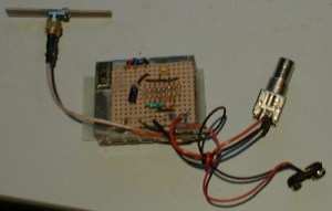
The external connections are an SMA connector for a simple antenna (the antenna is not as good as the patch antenna in a video sender, but the patch antenna would not fit in the rocket), a BNC connector for the video input signal, and a PP3 style power clip.
RESULTS
The set up I have was originally designed to return video footage from onboard a rocket - a task it does admirably. Pointing the antenna at a rocket that is no longer visible is a bit challenging, but with a bit of practice, is possible.
The port to port loss performance with the video sender transmitter and receiver pair, is around 92dB, at which point, a video signal transmitted to the monitor lost sync.
Factoring in the antenna gains this gives 110dB pathloss capability or an actual range of approximately 5.12 kilometres (3.2 miles) or just short of 17,000 feet.
For ground based installations, with no obstacles in the way, a range of a couple of miles at least is easily possible.
ONLINE REFERENCE LINKS
- The definitive guide to making a 2.4 GHz Helical Antenna
- http://www.oreillynet.com/cs/user/view/wlg/1124
- Range Reality Check
- http://www.netscum.com/~clapp/wireless.html
- Slashdot Antenna Discussion
- Robert Cringely Article #2
- Robert Cringely Article #1
- consume.net
- http://wirelessanarchy.com
- http://www.wlan.org.uk
- http://nocat.net
- http://www.promotek.com/car/MTV.htm
- Antennas enhance WLAN security
- http://www.g1mfg.com
DEAD TREE REFERENCE LINKS
Building Wireless Community Networks - Rob Flickenger, November 2001
http://www.oreilly.com/catalog/wirelesscommnet/index.html
